Sunday, April 12, 2009
Storage / Map and Flight Guide Pocket

I have found it quite difficult to organise the paperwork aspect of flying in a -4. With significant help from my wife I have constructed this easy access pocket for maps and flight guides. I first flew with it yesterday, and its a great if small success.
My battery is on the firewall so this front compartment, underneath the pocket, is for adjusting CofG and carrying heavier items when aft loaded. You can see it here also, without the map pocket.
As additional storage I have an easy access space under the RHS step.
Monday, April 21, 2008
The wings are on!
 Yesterday the wings went on without too much bother. Two of us did it in about 2 hours. That is to the stage where we had 4 of the large bolts in each wing and one of the outer AN4 that take the load.
I made one mistake. I have aileron push rod tube draft seals. They are on an ally frame on the outside of the fuselage with screws from the inside. The frame was upside down so the wing had to come far enough off to let us rotate the frame around the tube.
I had forgotten, since the trial rigging, just how close the wings and fuse come on the -4. Don't overestimate the space.
I guess the picture is of two ikons together; an RV4 and a Supercub. Double click as usual if you want a better picture.

It is a slow job putting all the bolts in. I have spent nearly two days at it now. I am stiff and bruised but the job is 95% done. I have put the bolts near the pilot seat cushion with the heads aft to save the cushion. The rest I have tried to arrange neatly, bearing in mind which way is easiest to do them up. VANS have overspeced all the AN3 bolts involved. There are some AN3-16 which could all be replaced by AN3-15, and similarly some AN3-17 which could be replaced by -16. As a result, as you can see there are plenty of washers involved. If you use the VANS supplied bolts be sure you don't tighten the bolts down to the end of the thread.
A couple of the NAS bolts were very hard to get in. There is no rhyme or reason as to why. Use plenty of grease. I also spilt quite a bit of ACF-50. It is not the worst thing to spill but I will have to get the degreaser out in due course.
I seem to be short of a couple of bolts and some washers. I will make a note and come back to this.

Here is another view of the centre section.
Much of my wiring comes through the wing spar beside the control column. I have yet to fix it up and out of the way. Once this is done there is room for both without interference.
In this picture you can just see the aileron draft boots. They are orange balloon fabric.

For completeness I have added a picture of the flap system and wing leveller.
The relay in the bottom left of the picture signals when the flaps are less than about 95% retracted.

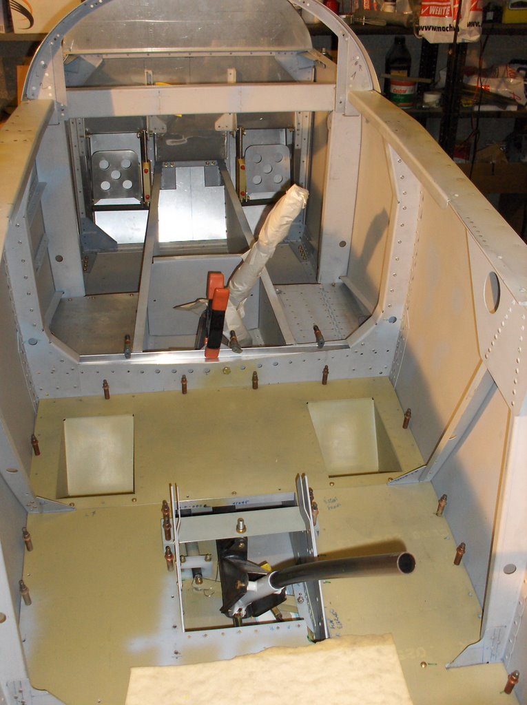
And here is how it all looks from where the pilot sits.
Tuesday, February 05, 2008
Throttle cable.
 I made up this bracket today to stand the throttle cable off the bulkhead. (I made a different design yesterday but had to throw that one away!)
The day closed with me puzzling which of the three holes on the carburetor lever arm I should be using. The middle one appears to give me 100% of the range but it is a very close thing. I would think the stops on the carb should be the limits, not the range of the control handle. I think I will ask for advice.
Postscript 6th Feb '08 - I worked on these cables again all afternoon. The range at each end appears to be just about identical. 100% of the range of quadrant movement gives you 100% range down at the carb. I want the carb to be controling the system, so what I plan to do is replace the washers in the quadrant with 1/8th sections of ally tube. This will incresae the range, at the quadrant by about 1/16th at each end.
The mixture control requires only about 95% of the quadrant range so is much easier to set up. Here is where I got to at the end of the afternoon at this end of the cables.
You can see the other end if you go here. http://gikonfwf.blogspot.com/2008/02/throttle-and-mixture-linkage.html#links.

Feb. 9th - The cables are almost finalised now. I have decided to make one change. Currently the throttle cable is a 48", but I will replace it with a 50" to give it a little more freedom. If the engine starts wagggling about I worry something will be stressed.
The prop is a 55" and the mixture a 60". I have put a first picture showing a little of the cable runs forward of the firewall here. http://gikonfwf.blogspot.com/2008/02/oil-cooler-oil-lines-and-control-cables.html#links
Thursday, January 17, 2008
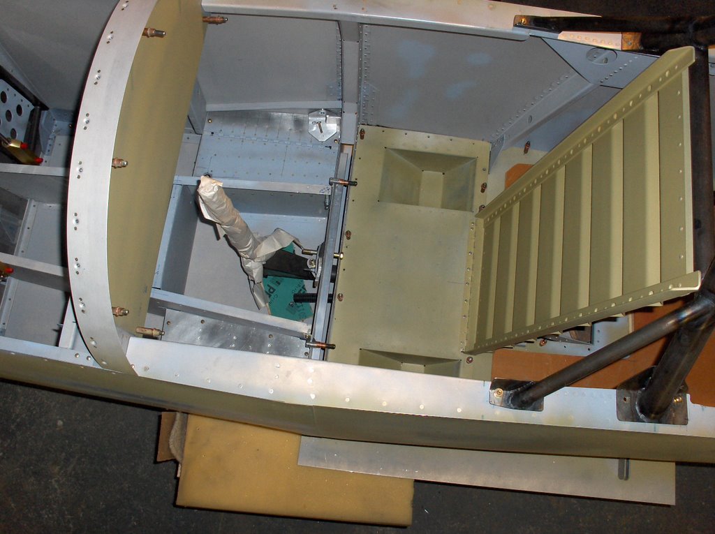
The fuel system inside the fuselage is complete.
 I installed the 'Red Cube' FT-60 fuel flow transducer today. It is installed between the electrical and mechanical pump, and after the Andair gascolator which I am using as a fuel filter. They ask for 5" of straight tube before the fuel enters and the same after. I haven't quite achieved the former. but doubt this will be a problem. If it is I will just have to bend up another bit of ally pipe.
I wonder why they have the connection wire exiting the top. I would rather it had come out of any other face!.

Here is another view.
The corrugated duct in this picture, is to take electrics through the cut out in the spar. There is just room for this without interfering with the control column. It will need to be stabilised very carefully when the wiring is complete.

I wanted to keep the forward compartment empty.
The battery is forward of the firewall. With the fuel related items above, located in the next compartment aft, with the stick, with the exception of the fuel pipe you see, I have this to use for a small bag, and also to adjust the CofG as necessary.
Labels: Fuel
Thursday, November 08, 2007
Tru Trak pitch servo
 After three weeks away travelling, its back to the -4. I installed the pitch servo. It is identical to the role servo, and presented equally well.
To install it, you replace the standard VANS bellcrank brackets with a pair provided by True Trak. This just requires some careful de-riveting and then riveting the new pair in. They are extended behind the bulkhead to support the back end of the servo.
After that it is very straightforward with all necessary holes already drilled in the supplied parts.

Here is a view from the other side. The note is to remind me that I have yet to adjust the pushrod length and install a nylock.
The weight of these servos continues to offend, but I have to say they are beautifully made.
My wife is determined to remain a passenger, not a co-pilot, so on longer journeys where I have to manage flying, navigation, map folding and airspace they will be invaluable.
As usual, if you want to see more detail double click the pictures.
Sunday, October 14, 2007
Tru Trak roll servo.
 I installed the Tru Trak role servo today. The servo is a beautifully made stepper motor. It is a bit on the heavy side but much more reassuring than the Navaid devices servo which I believe has been carried over to Trio.
 The kit comes together with the necessary mounting hardware, though I did have to trim about 3/16" off the bottom of the vertical bracket.
All the nuts, bolts and bearings are supplied, together with an already tapped push rod. I did have to make up a shim since the upper part of the bracket is resting on the angle that makes up the longeron, and the rest is resting against the vertical web. The motor clears the belly skin by about 1/8".

It is a bit of a tight fit, but once it is in it appears to just clear everything. The large washer outside the bearing arm on the servo comes within about 1/16" of the underside of the floor, but I guess that is enough.
The total movement of the arm is a little less than 2", which is very little but appears to be what Tru Trak expect.
There is a very slight drag from the stepper motor when you move the stick, though once the push rods an ailerons are connected I suspect this can not be detected.
Thursday, September 06, 2007
F-466 fairing

Several people have asked me about the F-466 fairing. It certainly confused me at one point. Not in date sequence, but here it is, installed. It is held on mostly with proseal.
Saturday, August 18, 2007
Strobe power pack.

I plan on a single strobe bulb on the top of the VS. This seems like a good location for the power pack. I will put the magnetometer for the compass in the wing tip, since they can't both live here.
Wednesday, April 04, 2007
Rear seat cont....
 A helpful tip from a US builder pointed me in the right direction, and I chamfered the top corners of the bulkhead flange and the seat rail so the seat could tip back all the way to the bulkhead. Once this was done things started to fall into place. The major difficulty was the quality of the fiberglass part. It is far deeper than the canopy rail. I cut it and re glassed it.
 Everything pretty much fell into place after that, though the seat is perhaps a little tighter than I intended at the top. I am not sure why, since I had a 1/8th " spacer in place throughout at the 12:00 position. Still better tight than flapping about, when flying solo in turbulence.
 While my wife likes flying as a pax she would much rather not touch the stick! For this reason I wanted secure storage for it, out of her way. Once the seat went in, its home became obvious. It hangs on a pip pin, and is held at the bottom by a spare flap block. It is clear of the rudder cable also.
Postscript 19th March '09
Some interest in the finished rear seat has prompted me to post this picture. The cushions are by Becki Orndorf, and she did a great job.


Monday, April 02, 2007
Rear Seat Installation
 This area is subject of an SB from VANS some 10 years ago. SB 97-05-1.
 I think the SB caused the steel triangular brackets to be added, and they were not there before. They are standard on my plans.
 I think the purpose of the bracket is to stop the bulkhead collapsing backwards, and letting the seat, and buba, fall across the elevator pushrod. It is less than clear, because the SB refers to several figures which are not included.
I am a bit confused though, as to how the weight of the passenger is to be transmitted from the seat to the bulkhead itself. It appears very crude if the intent is point contact like you see in the second picture. I wonder what others have done?
Tuesday, March 27, 2007
Fuel valve, gascolator and pipework.
 I now have a complete path for fuel from the left tank to the fuel pump. If you are surprised to see the gascolator in this picture I have explained my logic elsewhere.
I am always amazed how simple bending pipe is in theory, and difficult to get it just right, with no stress, in practice! This is my best shot.
The path for the RH tank pipe is more complicated, and I am debating if I want to use pipe, or hose. Hose has a weight penalty but I could get there in one which provides less opportunity for leaks.
In this picture the part lying on the centre of the floor is a doubler plate for a bent whip antenna, but none of that is yet installed.
The continuation of the piperwork from the fuselage wall, to the LH tank, is shown in this "Wings" entry of the blog.
Thursday, February 15, 2007
F-463 completed
 These brackets have been enormously time consuming. The problem is VANS plan is close to an irrelavancy, as I explained before. This is compounded by the practicality of the task. Do you drill from the inside to the outside, or vice versa? From the inside it is physically quite difficult. From the outside, the wing is in the way. Perhaps if I had an even smaller right angle drill.....
Finally though, they are just about complete. I say just about because, although I remembered to allow room for a fat rubber washer in front of the bracket, on the outside, where the fuel will enter the fuselage from the flop tube, I did not allow for it in the spacer on the inside.
Ideally, I will not bring the fuel into the fuselage at that point, but take it under the -463 and enter under the step. I am just not sure the pipe will bend that tight. We will see....

Sunday, February 11, 2007
F-463 tank brackets continued..

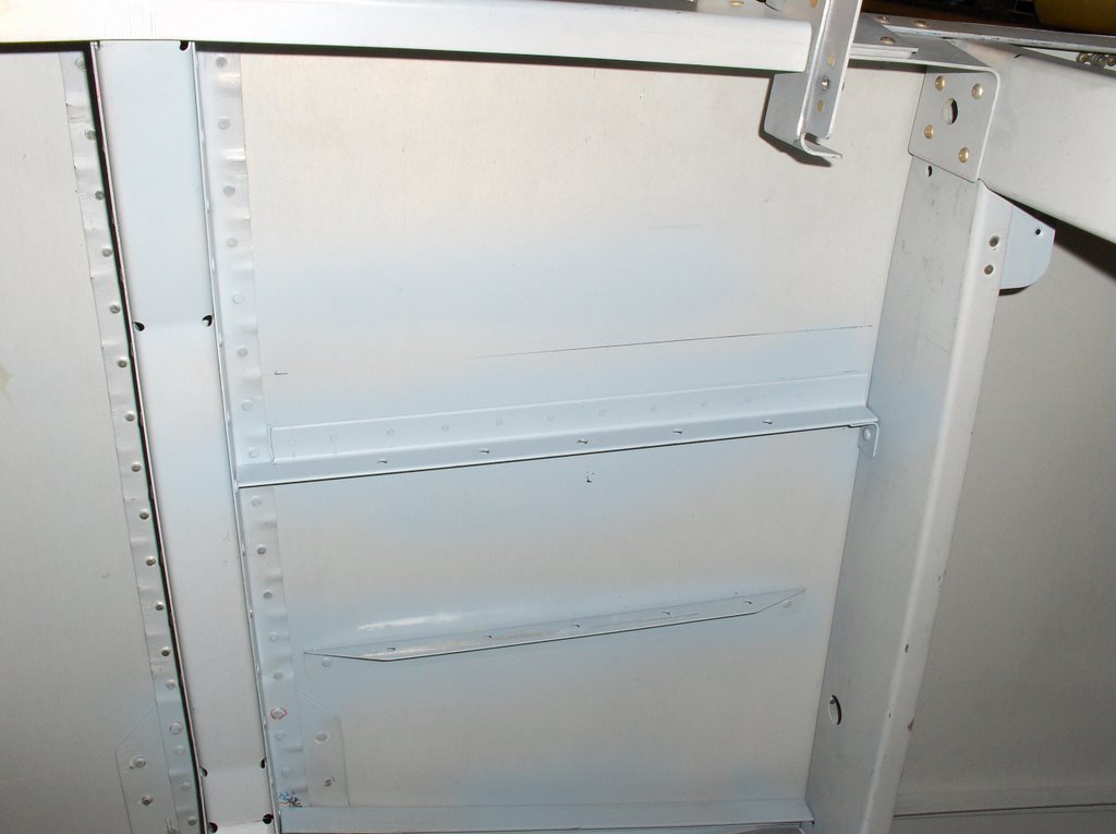
Finally the RHS F-463 is complete. It bears only a passing resemblance to those shown in the RV4 plan and a lot more to the RV9A plan which I was fortunate to have to hand. Here is the finished installation.
The problem is that the glass fairing sweeps in very close to the bottom bolt in this picture.
(I may yet have to grind a small amount of glass away.) If the bracket continued down so that it was bolted to the bottom longeron the fairing just could not fit on.
My solution - and I think most -4 builders - has been to put a vertical inside the fuselage to which the bracket can bolt. Here is a picture. The external bracket uses the upper two bolts. The other two holes are just to save a few grams.
I have also possibly installed the platenut bolt assembly that joins the wing to the fuse the reverse way around, but the plans are inconsistent on this point. For various reasons it made more sense to me done this way.
Here is the fairing slid almost into place to show the problem.
The problem is that the glass fairing sweeps in very close to the bottom bolt in this picture.
(I may yet have to grind a small amount of glass away.) If the bracket continued down so that it was bolted to the bottom longeron the fairing just could not fit on.
My solution - and I think most -4 builders - has been to put a vertical inside the fuselage to which the bracket can bolt. Here is a picture.
 The external bracket uses the upper two bolts. The other two holes are just to save a few grams.
I have also possibly installed the platenut bolt assembly that joins the wing to the fuse the reverse way around, but the plans are inconsistent on this point. For various reasons it made more sense to me done this way.
Here is the fairing slid almost into place to show the problem.

Monday, February 05, 2007
Control System
 The control system in the centre fuselage is almost complete. The points to note are:
1) Earlier on this blog - see Jan 12th '07 & July 8th '06 entry - I considered making the F-449 bracket so that it moved the stick further forward. In the end I have used the bracket as defined by the plans, but added a 1/8" shim between the bracket and the tie bar. This has moved the aileron pushrod tubes forward so they are almost central fore and aft, with respect to the pushrod tube hole in the sidewall. Making a firm decision regarding this, enabled me to match drill the 4 bolt holes for the rear mounting point of the stick assembly, in the centre of the picture.
2) I still have to increase the clearance of the push rod tube as it exits through the side skin. It is not blocking full movement as the rod gets to the limit of its travel but it is just touching. You can see this in the picture. With the stick fully over to the left the RH push rod tube just touches at the top of the exit hole. If I relieve this by 1/16th to 1/8th, that will cease. It is the same on the left side.
 3) I have had to grind quite a bit away from the hole above the rear spar, to ensure it does not touch, as you move the stick from side to side. I have an extra heavy bracket here to permit a 5th point for the PAX harness. I may need to grind a bit more off yet, to be sure it does not touch.
The flap mechanism went together quite easily, though the stressful bit lies just ahead; cutting holes in the exterior skins for the flap push rods.

Here is another picture of the fuse centre section.
Postscript - 12 May 07
 For completeness I have added a picture of the manual aileron trim unit.
The way it works (I think) is so.
The stick runs through the centre of the UHM block. The RHS long screw serves both to clamp the unit to the stick, as a pivot for the trim arm (green) and to provide some friction in the system. The LHS screw increases the friction in the trim arm. The springs attach to the lower part of the trim arm and the other ends to the sides of the compartment in which the stick is located. I presume some locking wire is used to adjust the length / tension.
So if you move the top of the trim arm to the left, the left spring tightens and the stick is offset left.
(If you click on the picture you can get a bigger one, which will enable you to see more detail.)
Thursday, February 01, 2007
F-463 Tank Brackets - read this before you make yours!
 One day this week when I was putting off the day when I had to drill the rear spar, I decided to cut out the brackets that attach the fuel tank to the fuse. I diligently marked out two, according to the plans, and worked away with my hacksaw. (Yes, I still haven't bought a band saw..its a hacksaw and file for me!)
When I had one roughed out almost to size I offered it up against the side of the fuse. It bears little relationship to what is needed.
I quickly reworked the other one to see if I had already gone too far to salvage it. The answer is probably 'yes' but it illustrates how wrong the plan is.
The bracket on the right is to plan, and bears no relationship to the relative positions of where the bolt holes need to go. The one on the left is to my design, but will probably have to be remade since it might be marginally short.
I am also advised that you need to take great care that they do not displace the wing fairing. Interestingly, in different places in the plans they are shown bolted to both the back and front of the 'ear' coming from the tank. The logical way, and I think VANS intent, is that they sit behind the 'ear'. If you have a flop tube it is probably essential in view of where the fuel exits the tank.
Labels: tanks wings
Friday, January 12, 2007
F-449
 I installed the F-449 bracket today. In fact I made up two of them, one per the plans, and the second one shown here. It locates the bearing, supporting the control column, 5/16th further forward. This appears to be preferential since it causes the aileron push rods to line up with the push rod hole in the side of the fuselage and wing rib. The standard bracket moves them 5/16th aft causing considerable filing to gain clearance for the push rod.
 I see very little downside. The only significant change is that the base of both sticks moves forward the same distance but I can not see why this might matter.
I will not drill the 3/32 bolt holes, that locate the rear control column support, or finalise the length of the push rod connecting the two sticks, until the ailerons have been installed, and no snag has been found.
Labels: controls
Thursday, January 11, 2007
Installing the Wings
This turned out to be a very easy task. We had expected it take the whole day. With a little grease on the bolts, and a very light wooden mallet, the whole job took less than 75 minutes without any swearing.
 The only slight hang up was getting the rear spar to fit between the two 'ears' in the side of the fuselage.
It is unclear quite how many bolts you need to safely support the wings. We took the decision to install 4 AN6 bolts into each wing root, together with one of the AN3 and AN4 bolts on each side, to take the weight.

While waiting for help with the wings, I had started to look at the canopy frame. I think it will be several months until I return to this task, since installation of the wings makes possible so many tasks that need to be done.
The canopy work will be much more easily undertaken when the wings are back off.
The wing installation continues under the the 'wings' section of this blog.
Labels: wings fuselage
Sunday, December 03, 2006
Static ports

I have used the rivets that VANS supply in their static kit. The tubes are glued in with blobs of a proseal competitor product. Once the ‘proseal’ that holds the rivets on is completely set, I just need to cut the tubes to length, and proseal them onto the rivet tails. I was quite negative about this static approach and nearly shelled out for a more expensive (and heavy) solution, but I now feel good about these. I will leave the static line aft of the bulkhead for now until the interior, forward of it, has been painted with a topcoat.
Forward Storage and Fuel System
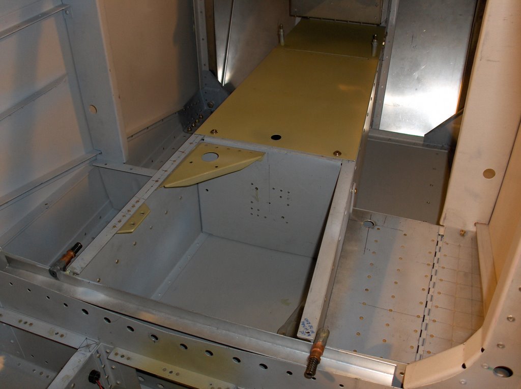 The forward storage is largely complete. With the battery forward of the firewall I will have a useful storage container between my feet as well as the smaller area under the right hand step. The large aft part of the storage lid is hinged (from behind the two clecos). I am not sure how many camlocs to use to ensure it does not vibrate. The hole is to put your finger through in order to lift the lid once the camlocs are released.
A secondary but important aspect of this storage area it will enable me to adjust CofG by re distributing heavy items between this area and the main baggage area.
In the next area back where the stick is located the bracket on the front left is the mounting for an Andair fuel valve, and behind that the next bracket will have an Andair gascolator bolted on. My approach to the gacolator is that it will just take the role of a filter. I do not plan to drain it before every flight. Testing for water will we be done at the wing drains since this is by far the most likely location for it to occur.

The array of rivets in the centre of the bulkhead (see center of upper picture) is reinforcing for nutplates to hold the Facit fuel pump.
Monday, October 02, 2006
The Front Seat Goes In.
 I made the front seat today. I had been very interested in the Jon Johansen seats, but the responsiveness of Flymore, his company, leads me to believe they are no longer interested to sell them. I begin to think I will go with the standard VANS seats.
I drilled a few extra holes in the angle, since in the spanwise direction it is way over engineered. It only saved a few grams though. You might just be able to see if you double click the picture.
At least now I can sit in and make aeroplane noises. Well, I didn't make the noises, but I did try it on for size, and was surprised how roomy it is in there. Perhaps I view it this way because I am used to glider (sailplane) cockpits. I am going to need a mountain of cushions to see out.
 Here is another picture. As you see, I have put some small brackets in on the rear face of the second bulkhead. My idea is to insert plastic thimbles into these and use them for the main elements of the wiring loom.
Postscript 19th March '09
And here is the finished front seat by Becki Orndorf.

Saturday, September 23, 2006
Drilling?
I never understand instructions like these in the plans. It is embarrassing to be building my second RV and still not fully understand this!
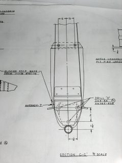
In the plan it says to drill "D". This is slightly less than .25", the size of an AN4 that will go in there.
Is the idea:
a) You drill "D" then hit the bolt with a mallet? Ouch!
b) You drill "D" then ream to .25"? Normally VANS call for a reamed hole if thats what they want.
Why not just say drill to .25"?

Perhaps someone will help me if I ask on Vansairforce.
Postscript 24/9/06
There were 2 or 3 really helpful comments came in on Vansairforce. If this subject interests you, see : http://www.vansairforce.com/community/showthread.php?postid=73740#poststop
Monday, September 04, 2006
Fuselage interior coming together.
 This picture gives a good general idea as to how far the interior of the fuselage has progressed.
The floors are all in place, and the cut out for the flap drive is complete. In the build manual it said to install the inner flap drive brackets with nuts since they were accessible. To my mind only accessible if you have the dexterity of an orang utang, so I have used a pair of nutplates at ALL four bearing locations. The mount for the rear control column bracket is 'floating' for now and awaiting a trial fit of the wings. It will be quite easy to secure that with nuts however when I can match drill the holes.
The left side floor is drilled #30, and I will install with LP-4 pull rivets. (They are lighter than nutplates.) The right hand side I have made removable, and installed #8 nutplates to secure it. These were difficult to install since you are working very close to the side skin which makes for great difficulty operating my Tatco. I have since learned that it is recommended these are installed prior to skinning the aircraft. I endorse this. A shame VANS don't mention it. I used some CCR-264SS-3-2 blind rivets in the most difficult places.
The reason I want the floor removable is I plan to have a wing leveler down there on the RH side, and will need accessibility.
Yes, if you are wondering, I have used 4 different etch primers. Mostly it is a biscuit colour, but there are also 3 different shades/brands of gray. From here on I will be down to 2 colours: biscuit ,and small jobs with a rattle can of gray.
 Looking aft I have found a way to fix the upper rear baggage bulkhead. I am not sure what others have done. I made up some little brackets that stand the panel forward 1/2" and secured with #8 nutplates.
The rest of the baggage compartment is complete, though not installed in this picture.
I re did the throttle mounting by installing two very simple brackets. I think it positions the throttle in the right area, provides the necessary strength and is the lightest implementation I can think of.
I seem to have a different view of weight from most. Perhaps I will sound off in RAMBLINGS.
![]()