Tuesday, June 27, 2006
Floors and Flaps
 Installing the floors progresses well. After preparing what seemed like a million holes the easy back riveting was quite rewarding.
Some issues have come up though:
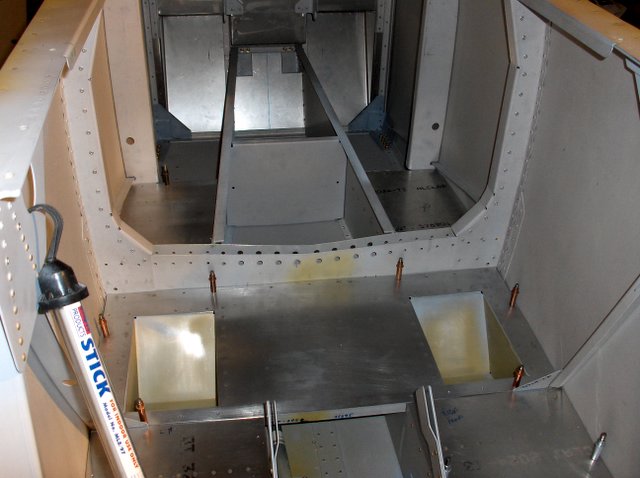
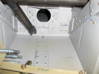
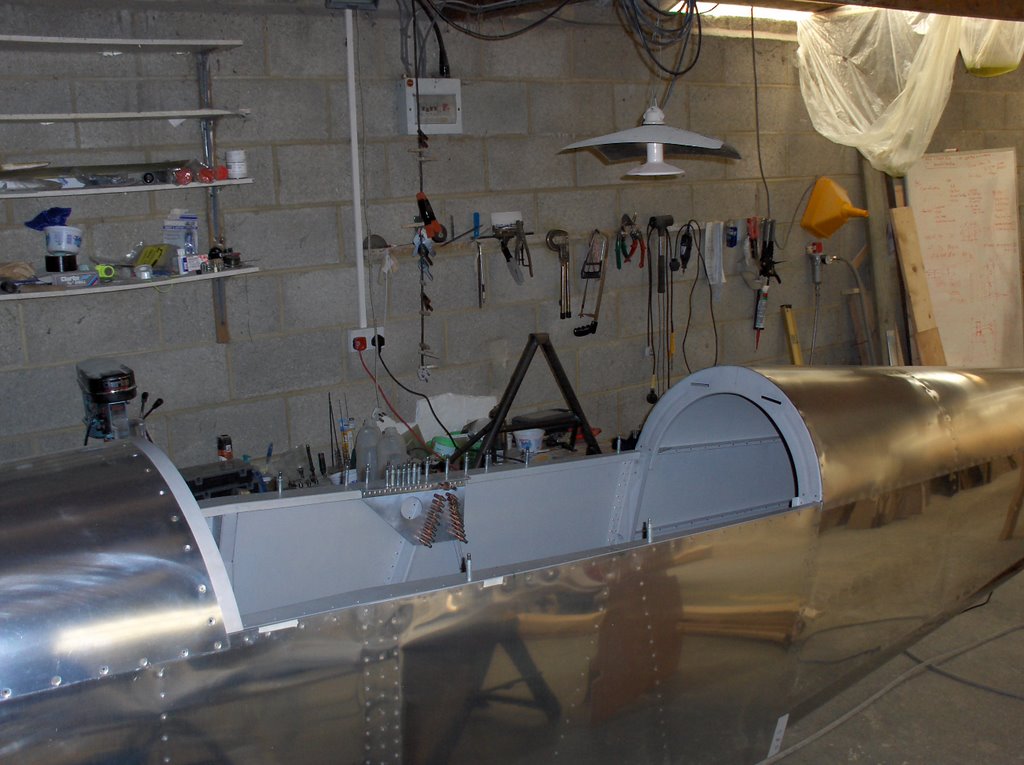
 First, here you are looking aft at the floor area where the passenger's bum will go. The flap drive is placed loosely in position. What VANS don't tell you in the instructions for the electric flap, is what they propose you should do about the floor that remains after you have removed the bit that interferes with the drive lug hanging down off the bottom of the shaft. Any one got a bright idea? Somehow just leaving it floating does not seem quite right.
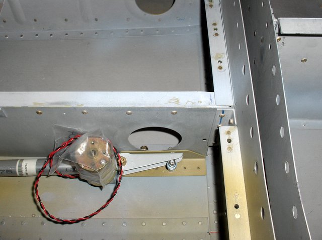 Second, I am really not sure what to do about the two bolts that go through the edge of the lightening hole. If I do them up tight it will crush the stamping which is rather ugly. Ideally one would make a shim but it is just two complicated a shape to be practical. The bolts are where the plans dictate so I cant be the first to run into this issue.
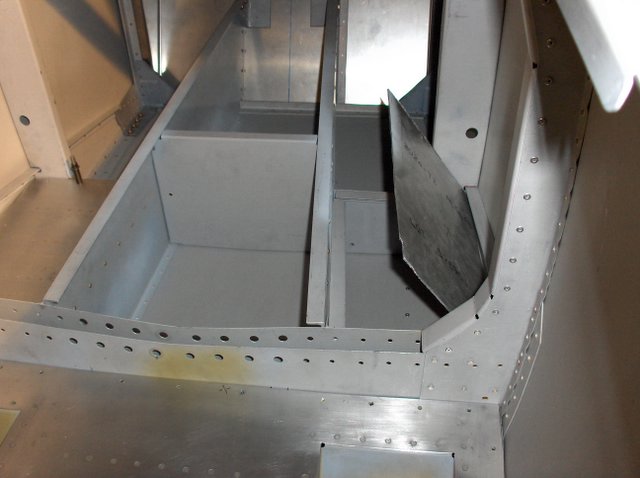 Finally, I have decided to use the space under the step on the right as a storage hidey hole for bits and bobs. Has anyone got a picture of how they implemented this? I think opening to the right is the most practical way, and probably hinging the part in line with the fuselage centerline about 1/3rd of the way from the outside skin at the bulkhead. Good design is never easy so I would rather steal an existing satisfactory solution.
Friday, June 23, 2006
Footwells complete
 The footwells were completed today. One of those jobs that appears to be a lot of work for what it is. Its mostly back riveting though which is always satisfying.
You can find a plan for these in the '24years of the RVator'. If you double click the picture I think you can probably read the dimensions off the enlarged version.
Thursday, June 22, 2006
Footwells
Although not supplied by VANS, even as an option, most RV-4 have footwells for the passenger's comfort. It is worth noting they are pretty well mutually exclusive with rear rudder pedals. (But then you don't build a -4 with the emphasis on someone else having all the fun!) Plans for these footwells can be found in 'RVator 24 years'.
 The footwell is riveted together from 3 bits of ally with simple bends. It then has to be set into the floor and a hole cut to size.
 Here it is now dropped into the floor. Its still looking a bit
ragged at the edges but nothing a file and patience wont sort out. The black tape is to protect it from the file.
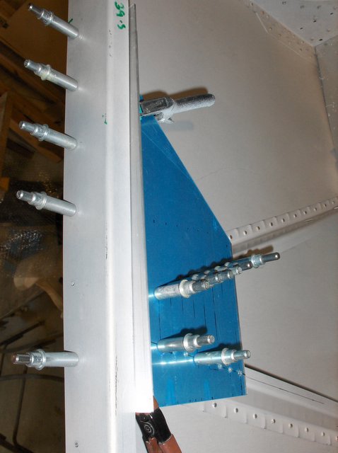
 This is the crucial bit. The footwells sit right behind the aileron pushrod path. Once the footwell is set in the floor you need to check the path for the pushrod is clear. Yes, it overlaps a little, but I think this is normal.
One irritation shows up in this picture. You can just see a nut. This is a part of the flap system. It is where it is meant to be according to VANS plans but if I tighten it up it will crush the stamped metal around the push rod hole. It probably doesn't matter, but its a bit ugly.
 The footwell is riveted together from 3 bits of ally with simple bends. It then has to be set into the floor and a hole cut to size.
 Here it is now dropped into the floor. Its still looking a bit
ragged at the edges but nothing a file and patience wont sort out. The black tape is to protect it from the file.
 This is the crucial bit. The footwells sit right behind the aileron pushrod path. Once the footwell is set in the floor you need to check the path for the pushrod is clear. Yes, it overlaps a little, but I think this is normal.
One irritation shows up in this picture. You can just see a nut. This is a part of the flap system. It is where it is meant to be according to VANS plans but if I tighten it up it will crush the stamped metal around the push rod hole. It probably doesn't matter, but its a bit ugly.
Tuesday, June 20, 2006
Flap drive system
Today I moved on to the flap drive system. I like mechanisms so this is where the fun really starts. The RV4 was originally designed with a manual flap system, however it has some draw backs, in particular its effect on passenger comfort. The electric flap system is therefore an option which was designed in afterwards. As you can see it uses the same flap drive mechanism as the other RV, but has an interesting lever system in view of the limited space.
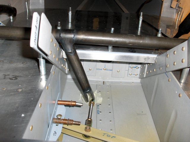
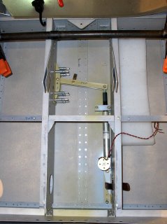 In this picture you see the drive mechanism on the RHS partially extended; perhaps 10 to 20% of its range. The fixing on the LHS is a pivot point. About 1/3rd of the way along the lever you see a bearing which when the flap motor causes the mechanism to contract moves at about 1/3rd of the rate with 3 times the force. This pulls on a lug attached to the flap actuator (black) and in turn will cause the flaps to be deployed when it is all connected up. The points to watch when you are installing this are that you don't let the motor get too high. The problem this causes is the drive mechanism when fully extended is very close to the floor. I have a shim under the white nylon guide block you can see on the RHS. This will I think ensure the bolt head never touches the floor.
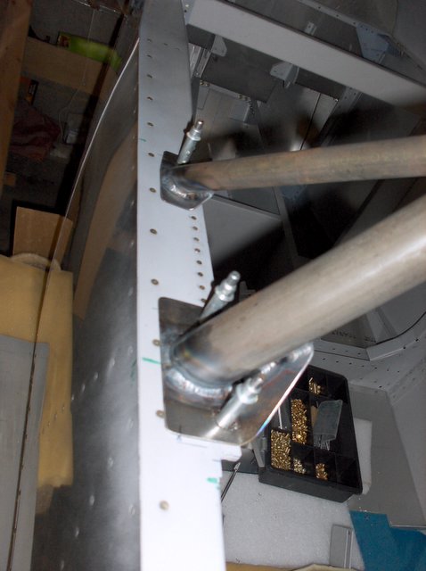
 Here the camera is nearly on the floor, looking aft. You can see the same bearing on the lever arm and the lug hanging down to which it will connect.
You can also see something interesting which is nothing to do with the flap mechanism. Projecting forward towards the camera is my solution to the rear passenger 5th point seat belt attachment point. Its not ideal in that the pull will be vertically upward, but I think it is quite beefy enough to do the job. It will need a thin shim between it and the underside of the cockpit floor.
There are quite a few 2 man jobs involved assembling this since some of the brackets need riveting on from underneath the fuselage.
 In this picture you see the drive mechanism on the RHS partially extended; perhaps 10 to 20% of its range. The fixing on the LHS is a pivot point. About 1/3rd of the way along the lever you see a bearing which when the flap motor causes the mechanism to contract moves at about 1/3rd of the rate with 3 times the force. This pulls on a lug attached to the flap actuator (black) and in turn will cause the flaps to be deployed when it is all connected up. The points to watch when you are installing this are that you don't let the motor get too high. The problem this causes is the drive mechanism when fully extended is very close to the floor. I have a shim under the white nylon guide block you can see on the RHS. This will I think ensure the bolt head never touches the floor.
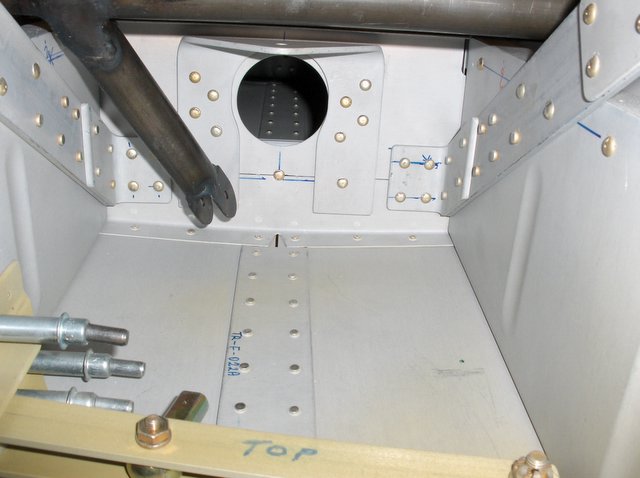 Here the camera is nearly on the floor, looking aft. You can see the same bearing on the lever arm and the lug hanging down to which it will connect.
You can also see something interesting which is nothing to do with the flap mechanism. Projecting forward towards the camera is my solution to the rear passenger 5th point seat belt attachment point. Its not ideal in that the pull will be vertically upward, but I think it is quite beefy enough to do the job. It will need a thin shim between it and the underside of the cockpit floor.
There are quite a few 2 man jobs involved assembling this since some of the brackets need riveting on from underneath the fuselage.
Friday, June 16, 2006
Roll bar structure continued.

I spent quite a bit of today working on the role bar support structure. The role bar is now clecoed in its final resting place. All the necessary edge distances are good.
The canopy rail is installed and the F-417 is riveted to the bulkheads. I will need to replace the remaining clecos with blind rivets. A few are allowed, though VANS encourages you to buck as many in the space between the skin and the F-417. I cant make that work.
 It is not clear that VANS intended the row of 3/32nd C/S rivets shown here, but it can't harm, and makes for a neater job with the rail pulled down tight on the skin.
Monday, June 12, 2006
Progress with the roll bar structure.
Support came flooding in from the -4 community regarding the roll bar support structure. Several pictures all of which agreed with each other, and not quite with the plans. That has enabled me to move forward with confidence. (Thanks everyone!)
 This is current status.
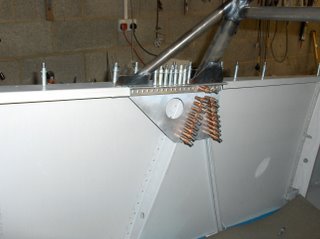 The angle is riveted to the F-417, and it sits nicely underneath the canopy rail. The forward inch or so even tucks in behind the rail which I think will make it look neater. I no longer need the shim I had made. The need for that went away when I 'unbent' the rail and was able to slide the angle up to its final location. It seems to be going together quite nicely now. The roll bar is sat there for the photo. I haven't touched it with the drill yet.
 I still have to cut off the excess material from the flattened out side rail.
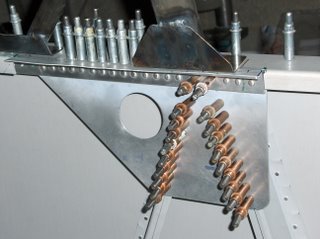
 In this picture you can see the angle did fit nicely behind the rail at the front end, though not by anything like the amount the plans indicated.
 This is current status.
 The angle is riveted to the F-417, and it sits nicely underneath the canopy rail. The forward inch or so even tucks in behind the rail which I think will make it look neater. I no longer need the shim I had made. The need for that went away when I 'unbent' the rail and was able to slide the angle up to its final location. It seems to be going together quite nicely now. The roll bar is sat there for the photo. I haven't touched it with the drill yet.
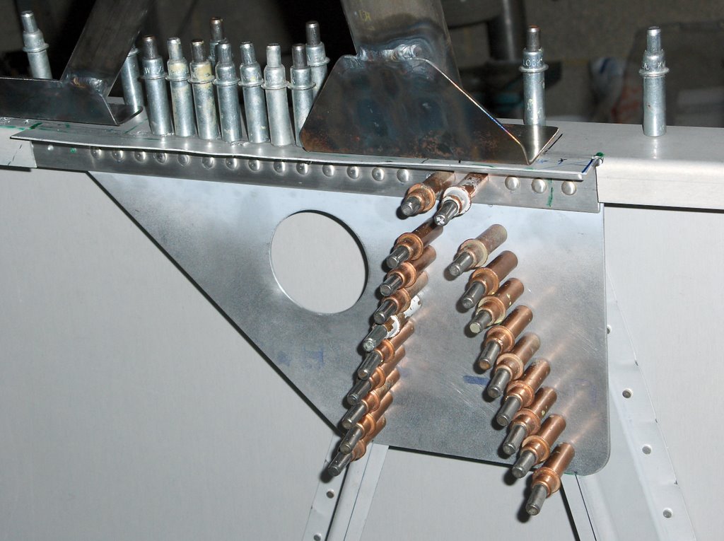 I still have to cut off the excess material from the flattened out side rail.
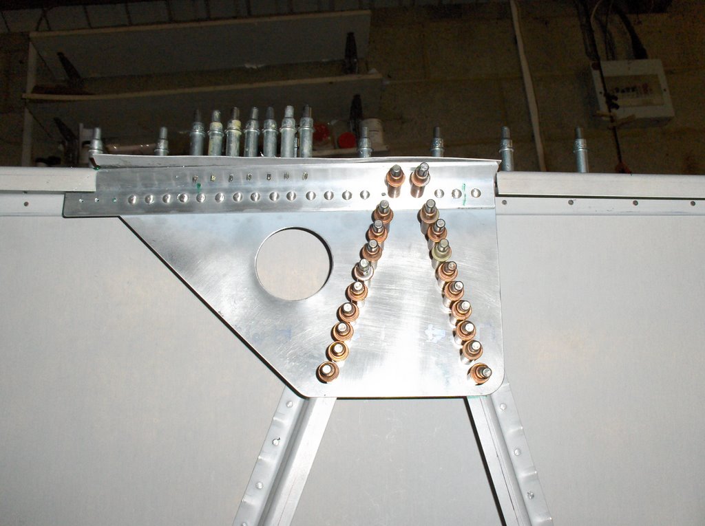 In this picture you can see the angle did fit nicely behind the rail at the front end, though not by anything like the amount the plans indicated.
Saturday, June 10, 2006
Rollbar Support Structure: F-416 & F-417
In the first picture I have assembled the F-417 and replaced the canopy rail F-416. I have then offered up the 12"*1"*1" angle. The problem is that according to the plans about 1/3 of the angle should be behind the canopy rail. Even at the front nearly a quarter inch is sticking out.
Read more »
![]()