Thursday, July 27, 2006
F-440 push rod
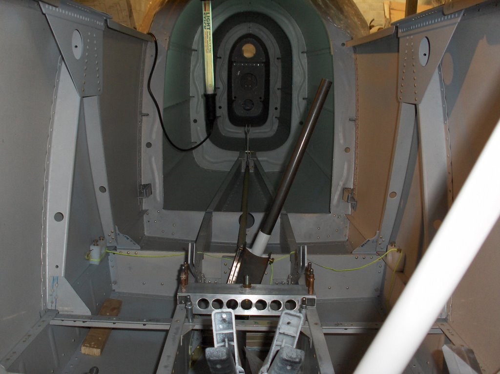 Getting the rear F-440 push rod in was a puzzle. It runs from the bottom of the rear stick to the bellcrank half way down the fuselage. You can just see it in this picture....
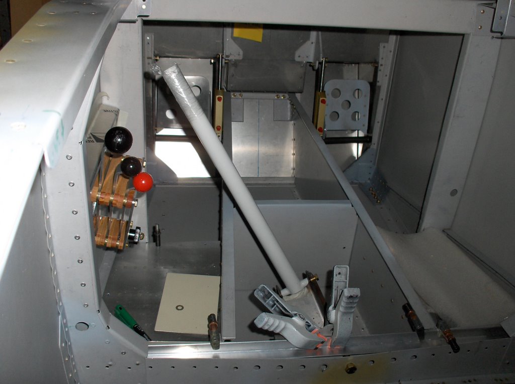
...and also in this one.
http://www.vansairforce.com/community/showthread.php?t=9550

 I asked what I should do, in the above link, and then did something different. I hope my fellow builders don't stop answering all my dumb questions in the future! They are a great source of confidence. My solution has been to cut a narrow gap in the top of the F-407 bulkhead. On the face of it this takes a lot of strength out of the structure, but in fact the plans show no join between the upper faces of this bulkhead above the push rod hole. (I might in fact put a removable strap to tie the two sides together. Then it will be stronger than shown in the plans.) With this bit removed, the rod just drops into place. I am advised that when I set the ailerons up I will have to enlarge the F-406 hole to allow full travel and this would also have allowed installation, but I was nervous of flexing the rod in view of some history. See : http://www.matronics.com/searching/getmsg_script.cgi?INDEX=31419437?KEYS=f-440?LISTNAME=RV?HITNUMBER=4?SERIAL=03075512942?SHOWBUTTONS=YES
As a complete aside, you can also see I have put a small drain hole in the floor. I hate doing this but I think water could leak in and collect here. Better it gets away. That's .0001 knots lost of my top speed!
 Finally, while I am on safety issues, I have included this picture. You can see that I have locking wire installed on the flap motor. DON'T FORGET THIS!!!!
I haven't done it up yet since I am sure these parts will go in and out many many times before I go flying!
Sunday, July 23, 2006
Don't forget to lock wire the flap motor!
 A posting on VANSairforce read,
"The other day on medium final my flaps (electric) went from full deflection to 0 deflection in an instant with a soft thud. I went around and checking things out and determined that I the motor was moving but the flaps weren't. An uneventful landing was made. "
See http://www.vansairforce.com/community/showthread.php?t=9458 for the full thread.
I was pretty sure I knew what the problem was, since I had built a -9A, and those plans ask you to lock wire the flap motor - see Detail E in the bottom LH corner.
Its a pity though that VANS don't have the same care for RV4 drivers. My flap motor plans for the -4 only came last year, and dont have this reminder! I had forgotten, and see no reason why I would have remembered in the next two years prior to flying. I hope this is helpful to someone else.

Postscript 14 April '07 - Finally a service bulletin has come out concerning this issue. See http://vansaircraft.com/pdf/sb07-4-12.pdf
Friday, July 21, 2006
Throttle Prop and Mixture Controls
I was planning to work on the elevator circuit but I was sidetracked into the power controls by access to a bending break. I will return to the stick assembly shortly.

The RV4 plans have poor definition as to where the quadrant should be mounted; or at least everyone disregards the position indicated as being crazy.
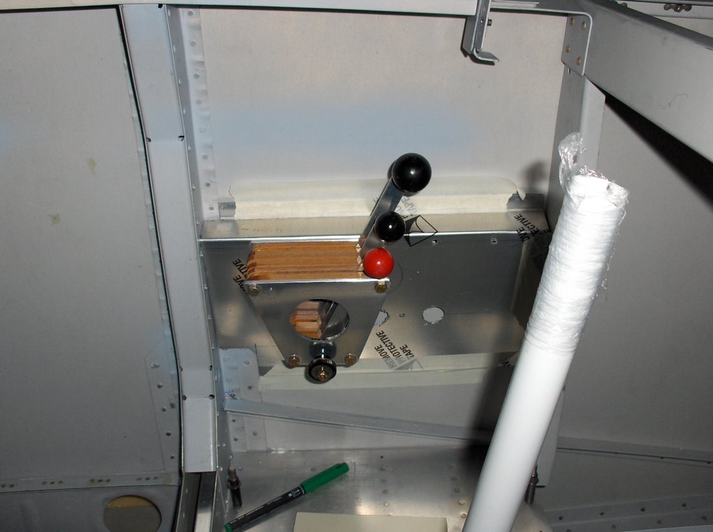
I made up this bracket. My idea was that I wanted the control canted outwards so my knuckles were not getting involved in the cockpit rail, but leaving maximum room for my legs. Now I am worried that the whole unit is to far out from the side skin.

I am also concerned about fore and aft positioning though I have allowed for this by drilling two extra sets of holes for the bracket to attach to.
Finally height is a concern though I can change things at the moment since the bracket is currently only held on with masking tape.

I think I will ask existing RV4 drivers for comments.
(What a shame they don't make the middle knob in blue. How cheap is that!)
The RV4 plans have poor definition as to where the quadrant should be mounted; or at least everyone disregards the position indicated as being crazy.
I made up this bracket. My idea was that I wanted the control canted outwards so my knuckles were not getting involved in the cockpit rail, but leaving maximum room for my legs. Now I am worried that the whole unit is to far out from the side skin.

I am also concerned about fore and aft positioning though I have allowed for this by drilling two extra sets of holes for the bracket to attach to.
Finally height is a concern though I can change things at the moment since the bracket is currently only held on with masking tape.
I think I will ask existing RV4 drivers for comments.
(What a shame they don't make the middle knob in blue. How cheap is that!)
Sunday, July 16, 2006
Rudder Pedals
 I spent a bit of time making the rudder pedals. The result has turned out OK, but the drilling accuracy of the various pivot holes is crucial. What is odd is the fact that the brake pedals and the rudder pedals do not operate in quite the same spanwise plane. You will see when you make them!
I also drilled the holes through the wing spar bulkhead for the rudder cables.
Progress has been slow since it is so hot!
 Next week's job is the elevator circuit. Today I trimmed the brass bushings to length, found all the parts, thought.......and decided it was too hot for further work. Went flying!
Thursday, July 13, 2006
F-449 Suggestions from VANS
I advised VANS of the problem I was having. This was their response.
"I've heard that in some cases the ears seem to be too far back like
this, I don't know why; maybe the plans, maybe the parts. It's usually
not necessary to do anything. The fore and aft movement of the
pushrods is negligible at the fuse side, and it doesn't matter if they
are centered in the hole or not, so long as they have decent
clearance (say 3/16" min). If they don't, the hole can be enlarged a
little.
You can leave the weldment mounted the 7/16 further forward, I
doubt it will affect much. The stick won't hit the panel if you move it
forward, it goes under it. It's possible the rear stick will hit the front
seat back though; you may need to increase the curvature to clear."
I have now made two brackets. The one to plan, which caused the problem, and one that moves the mounting bearing 7/16" forward. I tried to simulate the location of the aileron pushrod today to see how it will actually position through the holes. It's a smaller diameter rod than used on the -9A I had, so this will reduce the problem.
What I have decided to do is not drill the holes that locate the rear support for the control column, until I test fit the wings, and then decide which bracket I want to use. By adjusting the height of the front bearing (I cant find that defined in the plans) it might just be possible to use the VANS defined part, though it locates the 'ears' on the aft limit. My concern is the geometry of how the sticks fit, though I do not perceive this to be a major issue.
Saturday, July 08, 2006
Control Column, Stick and F-449 bracket.

I have run into a problem and I would like to hear how other -4 builders solved it. As you can see in this picture I have started to install the control column. (click on the picture and you will get more detail.)
I have followed the plans (I think, and the result is that the 'ears', to which the aileron push rods will attach, are sitting slightly too far aft to be central in the holes in the side of the fuselage. (This problem will compound the problem for the very tight space for passenger footwells.) Again I think the issue is probably generic (i.e. VANS) and not poor workmanship on my part. Has anyone met this problem before?
 In this picture you can see the F-449 bracket to which the control column is attached. It is spaced forward as indicated in the plans by a 1/4" spacer to simulate the steel tie bars (not sure of the correct name) that join the wings. However, you can also see in this picture that the 'ears' are sitting too far aft.
I can think of several ways to solve it, but as always, I worry about problems that will result that I have missed:
Solution 1 - use a thicker spacer. The down side of that is I will need longer NAS bolts which may/may not be available.
Solution 2 - (better) remake the bracket with a longer tongue so the bearing is moved forward. Will either of these solutions leave me with enough forward stick movement? Will the bracket still be strong enough?
Solution 3 - I am screwing up, and the problem lies elsewhere. (Unlikely because I have been warned of the problem in the past though I forget who told me.)
Solution 4 - Have the 'ears' re welded slightly further forward. (Not attractive to me.)
 In this picture you can see the 'ears' about 3/8" to the right (aft) of where they should be.
As a final note, yes, in the first picture you can see that I have made the bracket taller than normal with a hole in the top. This is for the harness 5th point.
Saturday, July 01, 2006
F-428 storage.
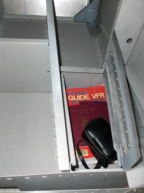 Finally I finished turning the F-428 step into a step, with storage space underneath. Its a useful size. I threw in what was to hand in the Supercub. A thick flight guide, two passports and a digital camera case, and there was room for plenty more. Certainly a flask of brandy!
 Here it is closed. I was hoping it would be less noticeable that it opened, but perhaps when it is all painted up and the canopy is on it will be.
The hinges and fore and aft bracing angle made it much heavier that the ordinary step, but then perhaps I have made it too strong.
I think I will put a 3/4" hole in the front left corner to facilitate opening and I will have to dream up a way of locking it shut. I don't want the brandy falling out when inverted. People will get the wrong idea.
I plan also to put a cover on the battery compartment and move that onto the firewall. It should all help put the C of G where I want it as well as provide storage for longer trips with Imelda.
![]()